

How Is Steel Plate Thickness Specified?
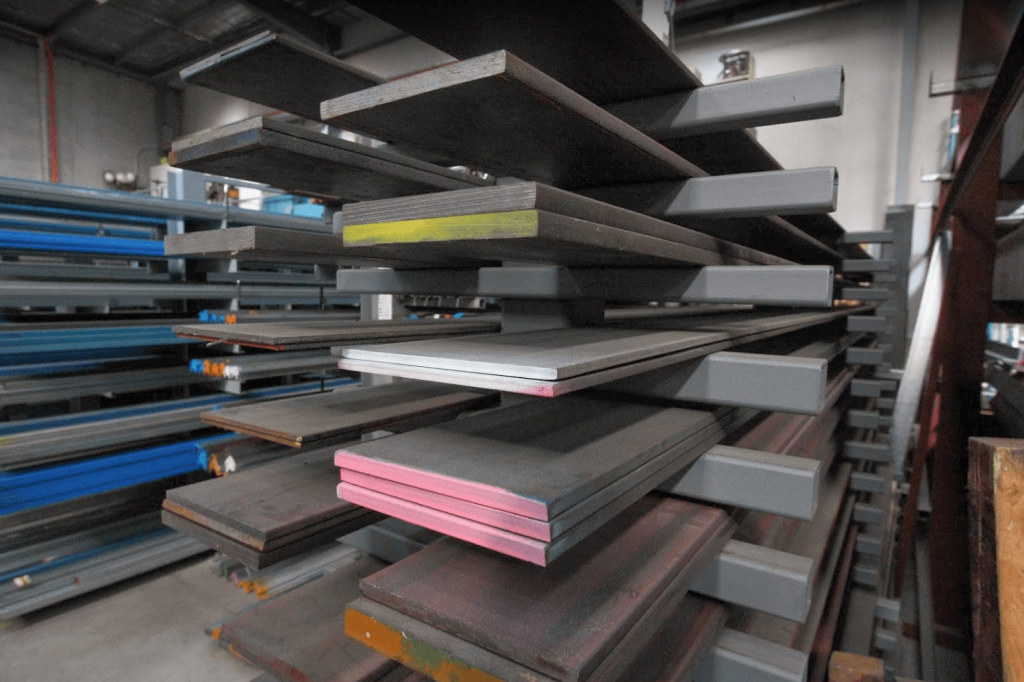
Steel Plate or structural steel is simply steel sheet material that can be customarily cut and welded to develop a more elaborate product. It is made by compressing multiple steel layers together into one; forming a plate of steel. It is commonly used to strengthen foundations and uphold mass units of weight like bridges. Alternatively, it provides a base for the construction of larger materials and non-workable parts.
Steel Plate is both corrosion and abrasion-resistant. It is manufactured to a much broader range of thicknesses than ordinary steel sheets. Plate steel is primarily used in applications where the super-structural framework and indestructible durability is required. Not only is it produced for structural purposes, but it can also be implemented for general repairs too. In addition to great reinforcement purposes, Steel Plate can withstand immense stress from the harshest natural environments, mainly, the ocean. It serves as a considerable advantage to the world of heavy machinery. Its durability allows for machining and wearable elements to last much longer.
Importance Of Thickness In Steel Plates
Hardness and tensile strength properties reduce as the plate thickness increases. The centerline microstructure of thin plates is fully martensite, and the fraction of bainite increases with increasing thickness. The reason for this is that the centerline of thicker plates undergoes slower cooling during manufacturing. Besides, the hardness profiles in the thickness direction have more fluctuations in the centre regions due to segregation as the plate thickness increases.
Thin plates have low impact toughness due to their fully martensitic microstructure. The impact toughness of thicker plates varies depending on the distance from the upper surface. Microstructures consisting of a mixture of bainite and martensite have the best impact toughness properties.
Hardness values decrease during the flame cutting process. The two-phase regions contain more newly formed martensite as the cutting speed and plate thickness reduce. However, the fine cementite particle structure diminishes in the tempered region as the bainite fraction increases with increasing thickness of the plates. Consequently, the hardness levels of thicker plates after the two-phase region are almost constant or slightly increased.
Residual stress measurements show that the residual compressive stress decreases in the surface region (< 1 mm) as the plate thickness increases. A lower cutting speed causes a lower tensile stress region in the thin plates. However, the residual tensile stress values are almost the same at a higher cutting speed and for all thicknesses.
Thicker plates tend to be more exposed to cracking. The susceptibility to cracking increases as the high residual stresses are combined with the manufacturing-induced, strong centre segregation that occurs in thick plates.
This shows that thickness plays a very important role in determining the hardness, tensile strength, toughness and much more of steel plates. So it becomes very crucial to know the thickness of the steel plate we are working with. Let’s now dive into determining the pivotal factor of a steel plate which is thickness.
How to Select Thickness Measurement Technology
Direct and indirect methods
Destructive vs. non-destructive methods
Often destructive methods allow the direct measurement whereas most non-destructive (non-contact) methods use indirect relations and, therefore, require calibration or reference parameters.
Conductive and non-conductive
Transparent and semi- or non-transparent
Reflective and non-reflective
Ferromagnetic and non-ferromagnetic

Eddy-Current Method
It is desirable to test the thickness of steel plates by the eddy-current method using screen-type converters. In testing thickness by the eddy-current method with a unilateral approach to the object, it is desirable to use a method based on recording the phase of the signal; this reduces the effect of fluctuations in the gap, improves the linearity of the characteristic of an applied converter, and increases the range of thicknesses measured.
To ensure the linearity of the characteristics, screen-type converters should be used with phase-type recording circuits. is the sensitivity of a screen-type phase converter to an increment in thickness equals Δϕ/t1=40°β. For serious nonuniformities in the electromagnetic properties of the material, it is desirable to use screen-type converters, with magnetic biasing of the test region employing a steady magnetic field, and an amplitude-phase recording circuit.
Ultrasonic Method
An ultrasonic thickness (UT) gauge can be used to measure the thickness of metal and many other solid materials. In maritime heritage work, this instrument can be used to measure the thickness of metal remaining in iron and ship hull structure and plating.
A UT gauge sends short pulses of very high-frequency sound waves from a hand-held probe in contact with the material and measures the time taken for each sound pulse to travel through the material, reflect off the back wall of the material then return to the probe. If the speed of sound in the material being tested is known then it is possible to calculate the thickness of the material by multiplying the speed of sound by half the total travel time.
Advantages:
It does not affect the material being tested
Direct measurement of thickness is made
It provides instantaneous results
Minimal processing of the measurements is required
Minimal expertise is required to collect the measurements
Access is needed to only one side of the material
Minimal preparation is required
The method is non-hazardous to the operator
The equipment is portable and easy to use
Some disadvantages
The ultrasound does not penetrate concretion so the surface of the metal must be cleaned
Tight coupling is needed between the probe and the metal
Materials that have rough surfaces are exceptionally thin or not homogeneous are difficult to measure
Cast iron and other coarse-grained materials are difficult to inspect due to low sound transmission and high signal noise
Weight Measuring Method
Knowing the layer area and the density of the layer material allows the determination of thickness by weight measuring. This is achieved either by measuring the weight difference of the structure of interest or by investigating the weight of a reference structure. Analysis and micro scales or other special disposition weight measuring methods are very precise, but allow very low loads and an in-situ application is difficult.
A common and even more precise and in-situ applicable method is the quartz monitor method. Quartz in the chamber next to the substrate is coated under the same condition. The quartz alters its oscillation characteristics depending on its weight which is monitored and evaluated. It is an extremely precise method that is also suitable for coating sequences. Another approach is the weight measurement of the consumed vapoured material. It is a simple but not very precise method. Furthermore, there is also chemical quantitative analysis which determines thickness by measuring the duration of a chemical reaction for detachment of the layer. The coulometric method determines the thickness in reverse electrolysis by measuring the changing potential. It is very precise but destroys the layer so it is mainly used for lab applications.

Radiometric Method
Measuring the thickness of steel plates during the hot rolling process is crucial for getting the necessary feedback to obtain the desired values at room temperature. The dilatation and the phase transformations of steel occur during heating and subsequent cooling and rolling strongly influences the results of thickness measurements. The radiometric method provides the necessary means for making real-time and fully automatized measurements of steel thickness during rolling if only the temperature correction is precisely known and taken into consideration. The experimental results concerning the relative variation of steel thickness and corresponding mass-thickness variation can be correctly explained employing the theory of metal dilatation correlated with the theory of nuclear radiation absorption when passing through metal or metallic alloy, such as steel.
Magnetic Gauging Method
Magnetometers can be used for all non-ferromagnetic coatings on ferromagnetic substrates. They are often used for rapid quality assurance of galvanic layers (like zinc, copper or aluminium) on steel or iron. Magnetometers evaluate magnetic fields induced by coils that are influenced by the distance to the substrate. Since this technique requires to contact the surface of the test material, it may impact the surface. Despite the simplicity of the approach, there are many issues to consider when contacting a layer as the probe position influences the measurement. Issues are too small samples, non-planar surfaces, roughness and misbalance of the probe. Carried out properly, the method allows thickness determination from few μm to few mm, if referenced to calibration samples.
Measurements can be done with various arrangements of one or more coils following the induction law and analyzing various effects. In a magnetically neutral background, the input and output currents match but if the core is exposed to a magnetic background field, then the signal changes due to varying saturation efforts. The rotating coil magnetometer induces a sine wave in a rotating coil and evaluates the amplitude of the signal. A hall voltage can be measured when an ashlar conductor or semiconductor is transduced by a current accompanied by a perpendicularly arranged magnetic field. The evaluation of the caused hall voltage provides an insight into the electrical properties, charge carrier density and mobility and, hence, the conductivity. A further approach is the adhesion strength measurement which analyzes the strength during the detachment of a permanent magnet and converts this into the thickness.
Cross-sectioning Method
Coating thickness can be measured by cutting the coated part and viewing the cut microscopically. It can also be determined by making a geometrically designed incision through the dry-film coating and viewing cross-sections with a scaled microscope. A special cutting tool is used to make a small, precise V-groove through the coating and into the substrate. Gages are available that come complete with cutting tips and an illuminated scaled magnifier.
While the principles of this destructive method are easy to understand, opportunities exist for measuring error. It takes skill to prepare the sample and interpret the results. Adjusting the measurement reticule to a jagged or indistinct interface is a source of inaccuracy, particularly between different operators, however, direct observation of these conditions is sometimes informative. This method is used when inexpensive, non-destructive methods are not possible, or as a way of confirming nondestructive results.
Optical Gauging Methods
Optical methods potentially provide a class of non-contacting measuring techniques with a certain specific combination of advantages. Firstly, optical techniques work basically by locating the physical surfaces of the strip to be measured, so that the measurement is of actual thickness and is not modified by the internal composition of the material. Secondly, optical measuring heads maybe not merely non-contacting but quite remote from the surfaces to be located, so that it is possible to allow for a degree of strip flap, thus avoiding the need for accurate strip location. Thirdly, the speed of response of an optical thickness gauge, limited fundamentally by the response of the photodetectors used, may be very rapid.
Optical systems are particularly flexible so that it is possible in principle to design thickness monitoring systems to cover any given range of thickness variation. A chief problem in the design of optical systems for thickness measurement is in achieving adequate rigidity of the mechanical framework. It is, however, possible to design optical systems which minimise the mechanical rigidity requirement.
Bottom Line
Steel plates must be of precise thickness specifications for use in applications which require superior strength and wear resistance, such as bridges, wind turbine towers, and ships.
A variety of recognized methods can be used to determine the thickness of steel plates. The method employed is often determined by the toughness, coating, substrate, the thickness range, the size and shape of the part, and economics.